
Frequency Response Measurement with Electroacoustics Toolbox 3
Measuring the Frequency Response of Your Audio Device
One of the most powerful tools in Electroacoustics Toolbox is the Dual FFT Analyzer, which is capable of measuring system transfer functions and even indicating the quality of the measurement. This tutorial focuses on using the Dual FFT Analyzer to measure the frequency response of the audio device that you use to measure other systems and devices. If you want to measure the frequency response, or impulse response, of a listening room for example, that measurement will be affected by the quality of the audio interface that you are using to make the measurement. Therefore, it is important to know how your measurements will be influenced by your audio interface.
When measuring the properties of some device, like its frequency response, that device is commonly referred to as the “device under test” or DUT. In this case, the DUT is actually the audio device that would normally be used to measure some other device or system.
Measuring Your Audio Device
- Connect your device to your Mac (if necessary, you may want to consult your device’s user guide or owner’s manual).
- Using a patch cable that is appropriate for the device you are using, connect one or more outputs of the device to one or more inputs of the same device. Figure 1 demonstrates the connections using an Echo AudioFire4 FireWire interface. It is important to keep in mind that what will be measured in this tutorial is actually the combined frequency response of the input channel, the output channel, and even the patch cable between them.

- Figure 1: 1/4″ plug patch cable
- Launch Electroacoustics Toolbox.
- Create a new project if one was not created automatically when the program launched.
- Click the Device IO button in the project window’s toolbar to open up the Device IO Setup window.
- In the Device IO Setup window, click on the name of the device you would like to measure in the Available Devices list. This will display the device’s properties in the lower portion of the window.
- Make sure the nominal sample rate is set high enough to capture the desired frequency range. For this tutorial, select 44100 or 48000 Hz.
- Create a new Dual FFT Analyzer tool. This can be accomplished by clicking the “+” button in the Dual FFT Analyzer row of the project toolbox, selecting Dual FFT Analyzer from the Tools menu in the project window’s toolbar, or by selecting New Dual FFT Analyzer from the Tools menu.
- Select the Live Inputs tab in the controls drawer at the bottom of the Dual FFT Analyzer window.
- Select the DUT (the device you previously configured in step 6) from the Input Device popup menu.
- In the measurement table below the Input Device menu, the first row will already be pre-filled for Measurement 1. For Measurement 1, change the channel in the Reference column to match the physical output channel connected in step 2, and change the channel in the Source column to match the input channel connected in step 2.
- If you connected multiple physical input/output channel pairs in step 2, click the “+” button above the measurement table to add an additional measurement for each additional channel pair and configure the Reference and Source channels as in the previous step.
- In the FFT tab of the Dual FFT Analyzer’s controls drawer, set the number of spectral lines to a value that will provide the frequency resolution you need. For the purposes of this tutorial, select 4410 spectral lines if your DUT’s sample rate is 44100 Hz or 4800 lines if your sample rate is 48000 Hz. The frequency resolution of your measurement can be determined by the selected frequency span (which is dependent on the sample rate) and the number of spectral lines. You can calculate the frequency resolution by dividing the frequency span by the number of lines (if guardbanding is turned off). For example, if the selected frequency span is 24000 Hz, and the number of lines is 4800, the frequency resolution will be 24000/4800 = 5 Hz. You can also view the current frequency resolution of the analyzer inside the analyzer’s info drawer, which slides out of the right-hand side of the analyzer’s window.
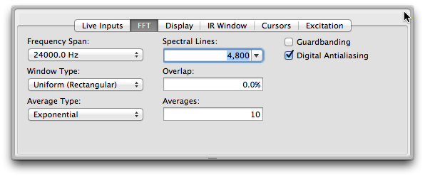
- Figure 2: Dual FFT Analyzer FFT Parameters
- Click on the Display tab of the Dual FFT Analyzer’s controls drawer to choose which kind of measurement to display. The name of each measurement can be edited by double clicking on it within the Name column of the table, either in the Display tab or in the Live Inputs tab.
- From the Function popup menu, select Transfer Function (H1) Mag to measure the magnitude of the DUT’s frequency response. Figure 3 shows the Function configuration for measuring the Echo AudioFire4.
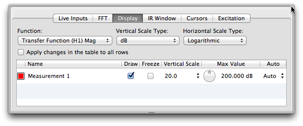
- Figure 3: Dual FFT Analyzer Function Selection
- If you are only using one output channel of the device, you can select that channel in the output channel popup menu in the Excitation tab of the Dual FFT Analyzer’s controls drawer. Then jump to step 22. Otherwise, follow steps 17 through 21 to configure as many Signal Generators as necessary to measure all the input/output channel pairs connected in step 2.
- Create a new Signal Generator tool.
- Select your DUT in the Output Device popup menu of the Signal Generator’s signal drawer (on the lefthand side of the Signal Generator window).
- Select the output channels corresponding to the physical output channels that you connected in step 2. Select the first output channel in the Left Output Channel box, and the second output channel in the Right Output Channel box. If you have connected more than two output channels for a multichannel measurement, you will need to create a new Signal Generator tool for each pair of output channels to be measured.
- Click on the Swept Sine (Chirp) tab in the Signal Generator window to display controls for establishing a frequency sweep excitation signal. Configure the swept sine generator similarly to that shown in Figure 4. The Upper Frequency should be half the selected sample rate, which corresponds to the Nyquist frequency.
- Click the “On” check box to enable the swept sine generator.
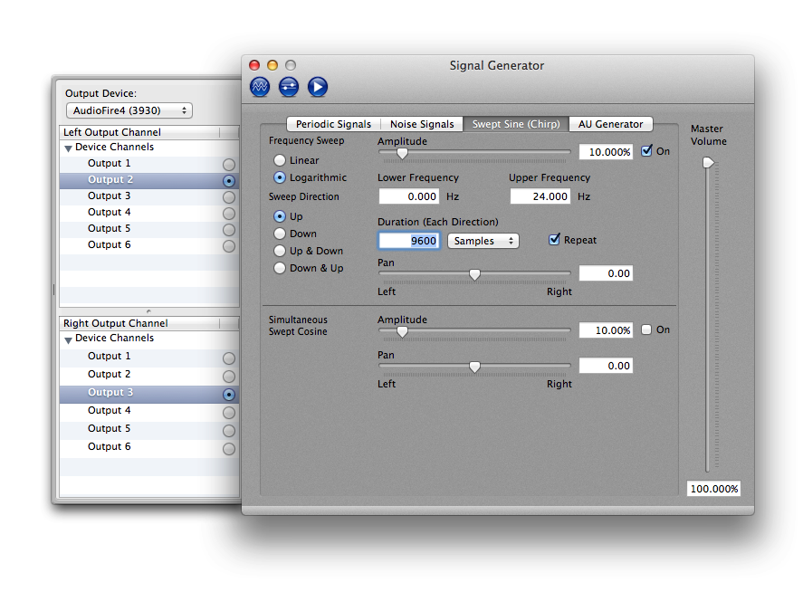
- Figure 4: Signal Generator Log Sweep Configuration
- Select the Dual FFT Analyzer window again.
- Go ahead and save the project now.
- Create a new Meter Bridge tool.
- Select your device in the Input Device popup menu of the Meter Bridge’s controls drawer (in the Live Inputs tab).
- Start the Meter Bridge.
- Make sure the Peak level type is selected in the Meter Bridge’s controls, then look to be sure none of the input channels are in danger of clipping (colored red at the top of the meter bar). If any of the input signal levels are too high, reduce the level in the Signal Generator (or the Excitation tab of the Dual FFT Analyzer).
- Start the Dual FFT Analyzer, either by clicking the start icon in the window’s toolbar, or by selecting Start Analyzer from the Control menu (or by typing Command-R).
- If you have one or more Signal Generator tools in your project, you can start all of them by selecting Start All Tools from the Control menu.
- After everything is running and the measurements have stabilized, you can stop the tools. (If you have Signal Generators running and choose to stop the tools individually, it would be best to stop the Dual FFT Analyzer tool first.) Figure 5 shows a plot, created by the Dual FFT Analyzer, which shows the frequency response of the Echo AudioFire4. The frequency response of the AudioFire4 is quite flat between 20 Hz and 20 kHz.
- Now that the frequency response magnitude has been measured, other measurements are just a menu selection away. Go back to the Display tab of the Dual FFT Analyzer and take a look at the different functions in the popup menu. All the data necessary to compute the various functions has already been acquired, so there is no need to run the analyzer again to measure the phase response. Once you have measured one of those quantities, you have essentially measured them all. All that’s left to do is change the selection in the popup menu.
- Capture your measurement, either by clicking the capture button in the Dual FFT Analyzer’s toolbar, or by choosing Capture Data from the Control menu.
- Save your project so you can review your measurement or export the data at another time.

- Figure 5: Echo AudioFire4 Frequency Response
RT @faberast: Frequency Response Measurement with Electroacoustics Toolbox 3: http://t.co/bGNwh0yG